Co właściwie robi drut zbrojeniowy w konstrukcjach z prefabrykatów betonowych
Drut zbrojeniowy utrzymuje razem klatki ze stali zbrojeniowej podczas układania i utwardzania betonu. W produkcji prefabrykatów betonowych zadanie to nie kończy się na wylaniu — ma bezpośredni wpływ na to, czy system podnoszenia prefabrykatów betonowych będzie działał bezpiecznie, gdy element opuści łoże betoniarskie. Źle zamocowana klatka przesuwa się pod wpływem wibracji, powoduje zmianę położenia prętów zbrojeniowych i zmniejsza głębokość osadzenia wbijanych kotw podnoszących. Rezultatem jest wkładka podnosząca, która nie jest w stanie unieść obciążenia znamionowego.
Krótka odpowiedź: drut zbrojeniowy to narzędzie wspierające konstrukcję, a nie tylko materiał porządkowy. W zakładach prefabrykacji produkujących panele ścienne, dwuteowniki, kolumny i belki grubość drutu ściągającego, wzór skręcenia i rozstaw ściągów wpływają na to, czy klatka wzmacniająca pozostaje zgodna z tolerancjami projektowymi przez cały cykl odlewania. Klatka, która przesunie się nawet o 10 mm od swojej pozycji projektowej, może naruszyć osłonę kotwy z pętlą do podnoszenia i zmniejszyć efektywny udźwig wysuwania o wymierny margines.
W tym artykule przedstawiono pełny obraz: typy i specyfikacje drutów, sposób interakcji drutu wiązałkowego z prefabrykowanym sprzętem dźwigowym, praktyczne wzory wiązania dla różnych geometrii elementów, dane dotyczące obciążenia, które mają znaczenie na miejscu, oraz ramy zgodności regulujące zarówno wybór drutu, jak i projekt systemu podnoszenia.
Rodzaje drutów zbrojeniowych i ich specyfikacje
Nie wszystkie przewody wiążące są takie same. Różnice między produktami są znaczące, gdy pracujesz wewnątrz formy prefabrykowanej, gdzie tolerancje są wąskie, a klatka wzmacniająca musi utrzymać swoją geometrię pod ciśnieniem wylewu betonowego, który może osiągnąć natężenie przepływu kilku metrów sześciennych na minutę.
Czarny wyżarzany drut wiązałkowy
Drut wyżarzany czarny jest najpowszechniej stosowanym drutem zbrojeniowym na świecie. Jest wytwarzany poprzez ciągnienie drutu ze stali niskowęglowej, a następnie wyżarzanie go w temperaturach od 650 °C do 750 °C w celu przywrócenia ciągliwości utraconej podczas procesu ciągnienia. Proces wyżarzania pozostawia powierzchnię ciemnego tlenku – stąd „czarną” – i sprawia, że drut jest na tyle miękki, że można go łatwo skręcić ręcznie lub za pomocą pistoletu do wiązania bez pękania.
Standardowe sprawdziany stosowane w pracach prefabrykacyjnych mieszczą się w zakresie od Średnica 16 (średnica 1,6 mm) do średnicy 18 (średnica 1,2 mm) . Wytrzymałość na rozciąganie zwykle mieści się w zakresie od 350 MPa do 550 MPa. Wydłużenie przy zerwaniu wynosi zwykle 20% lub więcej, co umożliwia czyste owinięcie drutu wokół przecinających się prętów bez pękania. Powszechnie dostępne szpule o masie 1 kg, 5 kg i 25 kg, przy czym 25 kg jest standardem na liniach do produkcji prefabrykatów.
Ocynkowany drut wiązałkowy
Ocynkowany drut wiązałkowy jest pokryty powłoką cynkową nakładaną metodą cynkowania ogniowego lub galwanicznego. Drut ocynkowany ogniowo ma grubość powłoki 45 do 85 mikronów , podczas gdy drut ocynkowany elektrolitycznie jest cieńszy i ma od 5 do 25 mikronów. W prefabrykatach betonowych przeznaczonych do zastosowań w środowisku morskim, konstrukcjach przybrzeżnych lub infrastrukturze narażonej na działanie soli odladzających, stosuje się drut ocynkowany, aby zapobiec plamom rdzy, które mogą przedostawać się na powierzchnię elementów architektonicznych.
Drut ocynkowany jest sztywniejszy niż drut wyżarzany czarny o tej samej średnicy. Nie stanowi to problemu w przypadku wiązania ręcznego, ale może powodować problemy w przypadku automatycznych pistoletów do wiązania, skalibrowanych do bardziej miękkiego drutu. Operatorzy często rezygnują z jednego rozmiaru — z 16 na 18 — przy przejściu na drut ocynkowany, aby zachować kompatybilność maszyny.
Drut wiążący ze stali nierdzewnej
Drut wiązałkowy ze stali nierdzewnej klasy 304 i 316 jest stosowany w specjalistycznych zastosowaniach prefabrykowanych, gdzie długoterminowa odporność na korozję ma kluczowe znaczenie – w konstrukcjach morskich, stacjach uzdatniania wody i najwyższej jakości panelach architektonicznych, gdzie jakość powierzchni musi pozostać nieskazitelna przez dziesięciolecia. Drut nierdzewny jest twardszy niż drut wyżarzany w kolorze czarnym; wytrzymałość na rozciąganie może przekroczyć 700 MPa . Wiązanie ręczne jest bardziej wymagające i rękawice są niezbędne, ponieważ końce drutu są ostrzejsze, a sprężynowanie jest bardziej widoczne.
Drut wiązałkowy pokryty PVC
Drut powlekany PCV jest czasami stosowany w prefabrykacjach, gdzie końcówka drutu nie może stykać się z powierzchnią formy i pozostawiać śladów rdzy na odsłoniętej powierzchni elementu. Powłoka zapewnia izolację elektryczną i zapobiega bezpośredniemu kontaktowi metalu z metalem ze stalowym szalunkiem. Typowa grubość powłoki wynosi od 0,3 mm do 0,5 mm. Jest to produkt niszowy, ale warto go poznać w przypadku architektonicznych projektów prefabrykatów, gdzie wykończenie powierzchni jest wymogiem umownym.
| Typ drutu | Średnica (mm) | Wytrzymałość na rozciąganie (MPa) | Wydłużenie (%) | Typowe zastosowanie |
|---|---|---|---|---|
| Wyżarzone na czarno | 1,2 – 1,6 | 350 – 550 | ≥ 20 | Prefabrykaty ogólne, elementy konstrukcyjne |
| Ocynkowane | 1,2 – 1,6 | 400 – 600 | 15 – 20 | Prefabrykaty morskie, przybrzeżne, architektoniczne |
| Stal nierdzewna | 1,0 – 1,6 | 600 – 800 | 10 – 15 | Offshore, uzdatnianie wody, architektura premium |
| Powlekane PCV | 1,2 – 1,6 | 350 – 500 | ≥ 18 | Panele architektoniczne z odsłoniętą powierzchnią |
Jak drut zbrojeniowy łączy się z System podnoszenia prefabrykatów betonowych
System podnoszenia prefabrykatów betonowych to skoordynowany zestaw elementów: wlewane kotwy lub pętle osadzane podczas produkcji, osprzęt do podnoszenia, taki jak sprzęgła lub szekle, belki rozporowe oraz dźwig lub wciągnik zapewniający siłę skierowaną do góry. Tym, co łączy to wszystko – dosłownie – jest klatka zbrojeniowa, do której przymocowane są kotwy. Drut wiązałkowy jest czynnikiem, dzięki któremu klatka utrzymuje swój kształt aż do momentu wylania betonu wokół kotew.
Kiedy punkt kontrolny przesunie się z pozycji przed lub w trakcie zalewania, konsekwencje nie będą kosmetyczne. Pętla do podnoszenia, która została zaprojektowana tak, aby była umieszczona na głębokości 80 mm od powierzchni i kończyła się na głębokości 55 mm, straciła znaczną część swojej zdolności do wyciągania. W zależności od mieszanki betonowej i geometrii elementu może to zmniejszyć dopuszczalne obciążenie robocze o 20% do 40% . W przypadku 10-tonowego prefabrykowanego panelu ściennego podnoszonego za pomocą czterech kotew tego rodzaju błąd stwarza realne ryzyko, że jedna lub więcej kotew ulegnie uszkodzeniu pod wpływem obciążeń dynamicznych występujących podczas podnoszenia.
Wbijane kotwy podnoszące i wymagania dotyczące ich mocowania
Najpopularniejsze kotwy wbetonowane stosowane w systemie podnoszenia prefabrykatów betonowych to:
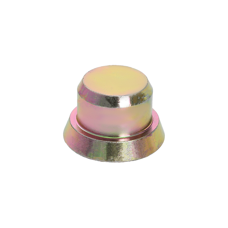
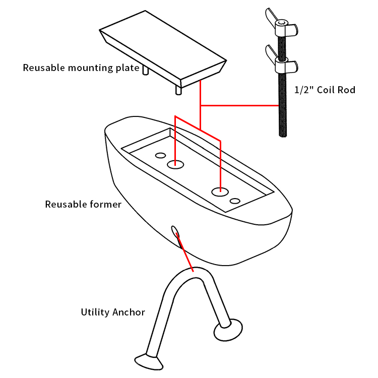
- Wkładki tulejowe (gniazda z krótkim gwintem odlane równo z powierzchnią)
- Wkładki zwojowe (gwintowane kotwy zwojowe do stosowania ze śrubami zwojowymi)
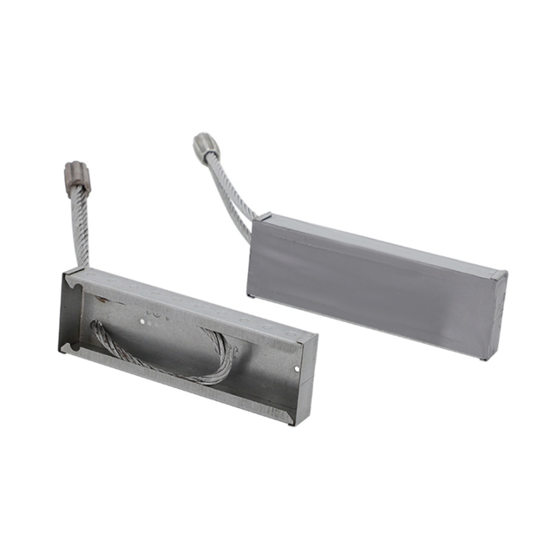
- Pętle do podnoszenia (pętle z drutu lub prętów zbrojeniowych wystające z górnej powierzchni)
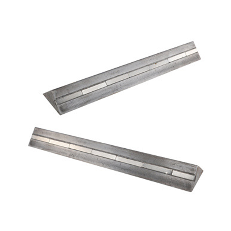
- Kotwy płaskie z wpustami ścinanymi osadzonymi w płycie
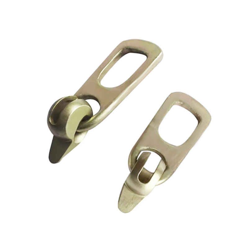
- Kotwy płytowe obrotowe do podnoszenia wielokierunkowego
Każdy z nich musi być mechanicznie przymocowany do klatki zbrojeniowej przed wylaniem. Drut zbrojeniowy jest standardową metodą mocowania. Wkładki tulejkowe są zwykle wiązane z sąsiednimi prętami za pomocą ósemki za pomocą czarnego, wyżarzanego drutu o średnicy 16, owiniętego co najmniej dwukrotnie wokół podstawy wkładki i skręconego aż do dokładnego dopasowania. Pętle do podnoszenia są zawiązane u podstawy w miejscu, w którym pętla wychodzi z betonu — drut zapobiega wpychaniu pętli głębiej pod wpływem nacisku betonu podczas wibracji.
Producenci kotew określają minimalne wymagania dotyczące ściągów w swojej dokumentacji technicznej. Halfen, Meadow Burke, Pfeifer i Leviat publikują instrukcje montażu, które opisują, ile potrzebnych cięgien i w jakich miejscach na korpusie kotwy. Przestrzeganie tych instrukcji nie jest opcjonalne — stanowi część łańcucha gwarancji i odpowiedzialności. Użycie drutu o niewłaściwej średnicy, niewystarczająca liczba skrętów lub pominięcie wiązania na kotwie całkowicie unieważnia certyfikat nośności znamionowej kotwy.
Obciążenia dynamiczne podczas podnoszenia i dlaczego integralność klatki ma znaczenie
Waga statyczna to tylko część historii. Prefabrykowany element betonowy podnoszony za pomocą dźwigu podlega dynamicznym współczynnikom wzmocnienia, które zwiększają efektywne obciążenie każdej kotwy. Większość systemów podnoszenia stosowanych w inżynierii prefabrykatów betonowych stosuje współczynnik dynamiczny wynoszący 1,3 do 2,0 w zależności od warunków dźwigu. 5-tonowy element podnoszony na placu budowy za pomocą pojedynczej kotwy w idealnych warunkach musi mieć tę kotwę o wytrzymałości co najmniej 6,5 tony, aby spełnić współczynnik dynamiczny 1,3 – zanim zostanie zastosowany jakikolwiek współczynnik bezpieczeństwa.
Oznacza to, że ruch klatki podczas odlewania, spowodowany luźnym lub brakującym drutem zbrojeniowym, może skutkować awarią systemu podnoszącego, nawet jeśli kotwa została wybrana prawidłowo dla obliczonego obciążenia. Dobrze zamocowana klatka nie jest luksusem — jest wymogiem dotyczącym ścieżki obciążenia.
Wzory wiązania dla prefabrykowanych klatek zbrojeniowych
Sposób, w jaki drut zbrojeniowy jest stosowany na przecięciach prętów zbrojeniowych, wpływa na sztywność klatki, czas potrzebny na zbudowanie klatki i jakość gotowego zespołu. W produkcji prefabrykatów betonowych, gdzie liczy się szybkość i precyzja produkcji, wybór wzoru ściągu jest praktyczną decyzją inżynierską, a nie tylko nawykiem terenowym.
Prosty krawat (krawat zatrzaskowy)
Krawat zatrzaskowy to najszybszy krawat do wykonania. Drut owija się po przekątnej wokół skrzyżowania, oba końce łączy się ze sobą, a haczyk lub szczypce skręcają je, aż drut wgryzie się w siebie. Całkowita liczba skrętów wynosi zazwyczaj od dwóch do trzech pełnych obrotów. Opaska ta nadaje się do niekonstrukcyjnych wewnętrznych przecięć w płytach i ścianach, gdzie główną funkcją jest montaż klatki, a nie precyzyjna kontrola położenia.
Krawat w kształcie ósemki
Opaska ósemkowa lub siodłowa owija drut w kształcie ósemki wokół obu prętów na przecięciu. Tworzy to bardziej stabilne połączenie, które jest odporne na obrót prętów względem siebie. Jest to preferowany krawat kotwice oraz w przypadku przecięć w pobliżu obwodu elementu prefabrykowanego, gdzie parcie betonu podczas zalewania jest największe. Krawat w kształcie ósemki zajmuje około 30% więcej czasu niż krawat zatrzaskowy, ale zapewnia znacznie lepszą stabilność pozycji.
Krawat krzyżowy (podwójny owinięcie)
Opaska krzyżowa podwaja drut wokół skrzyżowania przed skręceniem. Stosuje się je w punktach o dużym obciążeniu — narożnikach, zatłoczonych obszarach i miejscach, gdzie wiele prętów zbiega się w pobliżu kotwy podnoszącej. Niektóre specyfikacje prefabrykatów wymagają wiązania krzyżowego na co trzecim skrzyżowaniu prętów obwodowych, aby zachować geometrię klatki podczas transportu zmontowanej klatki ze stacji wiązania do formy. Ma to znaczenie w przypadku dużych elementów, takich jak podwójne trójniki i podstopnice stadionowe, gdzie przed umieszczeniem klatka może przejechać dźwigiem od 20 do 30 metrów.
Krawaty do pistoletu
Automatyczne pistolety do wiązania, takie jak Max RB441T lub Makita DTR180, rozwijają wstępnie przycięte zwoje drutu i wykonują wiązanie w czasie krótszym niż jedna sekunda na przecięcie. W przypadku dużych operacji prefabrykatów użycie pistoletu do wiązania skraca czas wiązania 60% do 70% w porównaniu do wiązania ręcznego, a stała liczba skrętów poprawia jednorodność. Ograniczeniem jest to, że pistolety do wiązania najlepiej sprawdzają się na płaskich matach; w trójwymiarowych zespołach klatek z małymi odstępami między prętami, w zatłoczonych strefach nadal konieczne jest ręczne wiązanie.
| Wzór krawata | Prędkość względna | Stabilność pozycyjna | Najlepsza aplikacja |
|---|---|---|---|
| Krawat zatrzaskowy | Szybko | Umiarkowane | Przecięcia płyt wewnętrznych |
| Rysunek ósmy | Umiarkowane | Wysoka | Kotwy kotwiące, pręty obwodowe |
| Krawat krzyżowy | Powolny | Bardzo wysoki | Narożniki, strefy kotwiczenia podnoszenia |
| Pistolet do krawatów | Bardzo szybko | Umiarkowane to High | Montaż mat płaskich, produkcja wielkoseryjna |
System podnoszenia prefabrykatów betonowych: przegląd komponentów i nośność
Zrozumienie systemu podnoszenia prefabrykatów betonowych oznacza zrozumienie każdego elementu łańcucha nośnego, od kotwy wbitej w beton po hak dźwigu na górze. Każde ogniwo w tym łańcuchu musi być przystosowane do tego samego minimalnego obciążenia. Słabe łącze w dowolnym miejscu systemu określa bezpieczną pojemność systemu.
Kotwy wbijane
Kotwy wbetonowane stanowią podstawę każdego systemu podnoszenia prefabrykatów betonowych. Ich nośność zależy od wytrzymałości betonu na ściskanie w momencie podnoszenia, głębokości zakotwienia kotwy, odległości od krawędzi, rozstawu kotew i kąta przyłożonego obciążenia. Większość producentów publikuje tabele obciążeń dla wytrzymałości betonu na ściskanie 20 MPa, 25 MPa, 30 MPa i 40 MPa. Typowa kotwa podnosząca o wartości znamionowej Maksymalne obciążenie robocze 5 ton (WLL) w betonie o ciśnieniu 30 MPa można obniżyć do 3,5 tony, jeśli podniesienie nastąpi, gdy beton osiągnie dopiero 20 MPa.
Dlatego też wytwórnie prefabrykatów zawsze sprawdzają wytrzymałość betonu przed oddaniem elementów do podnoszenia. Badania nieniszczące za pomocą młotka Schmidta lub badania wyrywania kostek towarzyszących utwardzanych wzdłuż elementu dają dane wytrzymałościowe potrzebne do potwierdzenia nośności kotwy.
Sprzęgła i haki do podnoszenia
Sprzęgła podnoszące łączą hak dźwigu lub belkę rozporową z zabetonowaną kotwą. W przypadku wkładek gwintowanych odpowiednie sprzęgło gwintowane jest włączane i blokowane przed podniesieniem. W przypadku pętli do podnoszenia przez pętlę przechodzi hak lub szekla. Sprzęgła muszą być kompatybilne z systemem kotwiczącym – zastosowanie sprzęgła z rodziny produktów innego producenta może zmniejszyć znamionową zdolność połączenia nawet o 50% ponieważ zmienia się geometria przenoszenia obciążenia pomiędzy korpusem sprzęgła a głowicą kotwiącą.
Belki rozporowe
Belki rozporowe stosuje się, gdy element prefabrykowany ma wiele punktów kotwiczenia, a hak dźwigu musi przykładać obciążenie w pionie, a nie pod kątem. Kąty zawiesia mają ogromne znaczenie: dwucięgnowy pas pod kątem 60 stopni między nogami zwiększa obciążenie każdej nogi poprzez 15% w porównaniu do pionowego . Przy kącie 120 stopni każda noga unosi więcej niż ciężar elementu, ponieważ geometria działa przeciwko systemowi. Belki rozporowe eliminują ten problem, utrzymując wszystkie nogi zawiesia blisko pionu.
W przypadku dużych elementów prefabrykowanych — belek mostowych o długości przekraczającej 20 metrów, podstopnic stadionów i dużych prefabrykowanych paneli elewacyjnych — belki rozporowe mogą być produkowane specjalnie w celu dopasowania do układu kotew określonego typu elementu. Te specjalnie skonstruowane belki są kalibrowane i testowane pod kątem obciążenia przed wprowadzeniem ich do użytku.
Zawiesia linowe i zawiesia łańcuchowe
Zawiesia linowe i zawiesia łańcuchowe to elastyczne łączniki pomiędzy belką rozporową a hakiem dźwigu lub bezpośrednio pomiędzy kotwicą a hakiem w prostszych podnośnikach. Obydwa posiadają ocenę WLL i podlegają obniżeniu w zależności od liczby nóg i kąta zawieszenia. Podczas podnoszenia prefabrykatów czterocięgnowe zawiesia łańcuchowe z ogniwami głównymi są powszechne, ponieważ rozkładają obciążenie na wszystkie cztery kotwy jednocześnie i można je dostosować do obciążeń asymetrycznych.
Obliczanie wymaganego udźwigu systemu podnoszenia prefabrykatów betonowych
Planowanie dźwigów dla prefabrykatów betonowych jest zadaniem inżynierskim, a nie decyzją dotyczącą oceny terenu. Sekwencja obliczeń jest zgodna ze zdefiniowaną logiką, która rozpoczyna się od masy elementu i przechodzi dalej, uwzględniając współczynniki dynamiczne, współczynniki bezpieczeństwa i geometryczne obniżenie wartości znamionowych, aż do osiągnięcia minimalnego udźwigu znamionowego wymaganego dla każdego elementu systemu podnoszącego.
Krok 1: Określ masę elementu
Beton normalny ma gęstość około 2400 kg/m3 . Lekkie mieszanki betonowe stosowane w niektórych zastosowaniach prefabrykatów mogą mieć ciężar zaledwie 1800 kg/m3. Masę elementu oblicza się na podstawie rysunków projektowych. Dla panelu ściennego o długości 6 m, wysokości 3 m i grubości 200 mm z betonu zwykłego: 6 × 3 × 0,2 × 2400 = 8640 kg, czyli około 8,6 tony.
Krok 2: Zastosuj współczynnik dynamiczny
Współczynnik dynamiczny uwzględnia siły przyspieszające podczas podnoszenia dźwigu, łącznie z podnoszeniem ze łoża odlewniczego i ustawianiem go na miejscu. PCI (Precast/Prestressed Concrete Institute) i podobne normy zazwyczaj określają współczynnik dynamiczny 1,5 dla normalnych warunków podnoszenia w środowisku prefabrykatów i do 2,0 w przypadku dźwigów dźwigowych wymagających poziomego przemieszczania się na duże odległości lub dźwigów przy wietrznej pogodzie. Zastosowanie 1,5 do 8,6-tonowego panelu daje obciążenie dynamiczne 12,9 tony.
Krok 3: Zastosuj współczynnik bezpieczeństwa
Współczynniki bezpieczeństwa elementów systemów podnoszenia są określone przez normy takie jak EN 13155 (osprzęt do podnoszenia ładunków niestałych), AS/NZS 4991 oraz lokalne przepisy dotyczące dźwigów i osprzętu. W przypadku kotw i sprzęgieł wbetonowanych współczynnik bezpieczeństwa wynosi 4:1 ponad znamionowe obciążenie awaryjne jest powszechnie stosowany, aby dotrzeć do WLL. Jest to już wbudowane w opublikowaną przez producenta kotwy tabelę DOR, więc zadaniem planisty jest zapewnienie, że opublikowany DOR przekracza obciążenie dynamiczne.
Krok 4: Uwzględnij liczbę punktów zakotwiczenia i rozkład obciążenia
Obciążenie dynamiczne o masie 12,9 tony jest rozłożone na wszystkie aktywne punkty kotwiczące. Jeżeli w 8,6-tonowym panelu ściennym zastosowano cztery kotwy rozmieszczone symetrycznie, każda kotwa teoretycznie udźwignie 3,2 tony. Jednakże praktyka inżynierii systemów dźwigowych uznaje, że idealny rozkład obciążenia w czterech punktach jest mało prawdopodobny ze względu na tolerancje w rozmieszczeniu kotew i umiejscowieniu haka dźwigu. Powszechnym, konserwatywnym założeniem jest to, że tylko trzy z czterech kotew przenoszą obciążenie w danym momencie, co oznacza, że każda kotwa musi mieć odpowiednią charakterystykę 12,9 / 3 = 4,3 tony DOR .
Praktyczne zastosowanie drutu wiązałkowego wokół kotew podnoszących
Prawidłowe nałożenie drutu zbrojeniowego wokół kotw podnoszących wymaga większej uwagi niż wiązanie standardowych skrzyżowań prętów. Kotwa jest elementem krytycznym pod względem obciążenia i jej położenie względem powierzchni betonu oraz otaczającego zbrojenia musi być dokładne.
Procedura mocowania wkładki tulei
Wkładki tulejowe to cylindryczne lub stożkowe gwintowane gniazda, które są odlewane równo z powierzchnią betonu. Są one zazwyczaj wykonane z żeliwa sferoidalnego lub stali i mają przyspawany do nich kołnierz bazowy lub pręt zbrojeniowy w celu zakotwienia w masie betonowej. Procedura wiązania drutu dla wkładki tulejkowej jest następująca:
- Umieścić wkładkę w odpowiednim miejscu na powierzchni formy, upewniając się, że otwór gwintu jest uszczelniony piankową zatyczką, aby zapobiec przedostawaniu się betonu.
- Przeprowadź pętlę z czarnego, odprężonego drutu o średnicy 16 przez mocowanie podstawy wkładki i wokół najbliższego pręta podłużnego.
- Dodaj drugą pętlę drutu wiążącego wokół najbliższego pręta poprzecznego, prostopadle do pierwszego.
- Mocno skręć oba krawaty za pomocą narzędzia haczykowego – co najmniej trzy pełne obroty. Przytnij końcówkę do 20 mm i zagnij ją płasko, aby uniknąć kontaktu z powierzchnią formy.
- Przed rozpoczęciem wylewania sprawdź, czy wkładka jest zlicowana z powierzchnią formy – ani wyniesiona, ani wgłębiona.
Procedura wiązania pętli do podnoszenia
Pętle do podnoszenia to pętle z drutu lub prętów zbrojeniowych, które wystają ponad górną powierzchnię prefabrykowanego elementu i są zaczepiane za pomocą sprzęgła lub szekli dźwigu. Ich osadzone nogi należy zawiązać, aby zapobiec wypchnięciu pętli podczas wibracji betonu.
- Umieść pętlę w miejscu projektowym, tak aby osadzone nogi przebiegały równolegle lub krzyżowały się z głównymi prętami wzmacniającymi, jak określono na rysunku projektowym.
- Przywiąż każdą osadzoną nogę do najbliższego pręta wzmacniającego za pomocą ósemki w co najmniej dwóch punktach wzdłuż każdej nogi.
- Jeśli pętla ma podstawę lub rozstawioną stopkę, przymocuj płytkę do co najmniej dwóch prętów za pomocą opasek krzyżowych.
- Przed wylaniem upewnij się, że wysokość występu pętli nad górną powierzchnią jest zgodna z rysunkiem.
Typowe błędy, których należy unikać
- Używanie drutu o mniejszym rozmiarze (20 mm lub mniejszego) do mocowania kotw — drut rozciąga się pod wpływem wibracji betonu i umożliwia ruch kotwicy.
- Wiązanie tylko do jednego pręta, jeśli określono dwa prostopadłe połączenia — utwierdzenie w jednej osi umożliwia obrót.
- Nadmierne skręcenie drutu wiązałkowego aż do zatrzaśnięcia – zerwane wiązanie na kotwie zapewnia zerowe utwierdzenie i należy je wymienić przed wylaniem.
- Pozostawienie długich końcówek drutu stykających się z powierzchnią formy powoduje powstawanie śladów na powierzchni, a na elementach architektonicznych widoczne plamy rdzy po wyjęciu z formy.
- Pomijanie ściągów na kotwach, które wydają się „stabilne” w formie – wibracje betonu podczas zagęszczania mogą przesunąć nawet pozornie stabilne elementy o kilka milimetrów.
Normy i zgodność dla drutów zbrojeniowych i prefabrykowanych systemów podnoszenia
Zarówno druty zbrojeniowe, jak i systemy podnoszenia prefabrykatów betonowych podlegają normom technicznym. Zgodność z tymi normami w przypadku projektów budowlanych nie jest opcjonalna – jest warunkiem wstępnym objęcia ubezpieczeniem, zatwierdzenia przez organy regulacyjne i ochrony od odpowiedzialności producenta. Odpowiednie standardy różnią się w zależności od regionu, ale kluczowe odniesienia są spójne pod względem wymagań.
Normy dotyczące drutu zbrojeniowego
- ASTM A82 / A82M (USA): Standardowa specyfikacja drutu stalowego gładkiego do zbrojenia betonu – dotyczy drutu stosowanego do produkcji drutu ściągowego.
- BS EN 10218 (Europa): Drut stalowy i wyroby z drutu – ogólne metody badań, obejmujące badanie wymiarów i właściwości mechanicznych.
- GB/T 343 (Chiny): Standardowy drut ze stali niskowęglowej ogólnego przeznaczenia, szeroko stosowany przez chińskich producentów drutu wiązałkowego.
- JIS G 3532 (Japonia): Norma dotycząca drutu ze stali niskowęglowej obejmująca drut, z którego produkowane są produkty z drutu wiązałkowego.
Normy dotyczące systemów podnoszenia w prefabrykatach betonowych
- EN 13155:2003 A2:2009 : Nienieruchome osprzęt do podnoszenia ładunków – wymagania bezpieczeństwa dotyczące kotew wbijanych i sprzęgieł podnoszących stosowanych w Europie.
- Podręcznik projektowania PCI, wydanie 8 : Podstawowe źródło informacji na temat projektowania prefabrykatów i betonu sprężonego w Ameryce Północnej, obejmujące pełny rozdział dotyczący obsługi, transportu i montażu, obejmujący projektowanie systemów podnoszących.
- JAK 3850 (Australia): Norma dotycząca konstrukcji z betonu uchylnego, która obejmuje wymagania dotyczące wkładek podnoszących, najwyższej jakości prętów i minimalnej wytrzymałości betonu wymaganej przed podnoszeniem.
- OSHA 29 CFR 1926.753 (USA): Obejmuje wykorzystanie dźwigów i żurawi wiertniczych w budownictwie, w tym wymagania dotyczące kontroli olinowania i kwalifikacji operatora, które mają zastosowanie do dźwigów prefabrykowanych.
W praktyce dokumentacja zgodności dotycząca operacji podnoszenia prefabrykatów obejmuje plan podnoszenia elementu, tabele DOR producenta kotwy odnoszące się do wytrzymałości betonu elementu, protokół kontroli montażu kotwy przez stronę trzecią oraz certyfikację dźwigu i sprzętu do olinowania. Drut zbrojeniowy jest częścią tego obrazu w protokole z inspekcji klatek, który powinien potwierdzić, że wszystkie kotwy zostały zamocowane zgodnie ze specyfikacją przed zalaniem.
Szacunki zużycia drutu zbrojeniowego dla projektów prefabrykowanych
Kierownicy projektów i zespoły zakupowe muszą dokładnie oszacować zużycie drutu zbrojeniowego, aby uniknąć opóźnień w produkcji spowodowanych niedoborami materiałów. Zużycie drutu zależy od rozstawu prętów, średnicy prętów, grubości elementu i zastosowanego wzoru wiązania. Ogólna zasada branżowa dotycząca standardowych prac prefabrykowanych brzmi: 8 do 12 kg drutu ściągającego na tonę stali zbrojeniowej . W przypadku ciasno rozmieszczonych klatek w elementach konstrukcyjnych z małymi odstępami między prętami (środek 100 mm) zużycie może osiągnąć 15 kg na tonę.
Przykład praktyczny: produkcja prefabrykowanych paneli ściennych
Zakład prefabrykatów produkujący 50 paneli ściennych tygodniowo, każdy zawierający 180 kg stali zbrojeniowej, zużywa 50 × 180 = 9000 kg prętów zbrojeniowych tygodniowo. Przy zużyciu 10 kg drutu ściągającego na tonę prętów zbrojeniowych tygodniowe zapotrzebowanie na drut ściągający wynosi 90 kg . W kręgach 25 kg, czyli około 4 kręgi tygodniowo. Większość zakładów produkujących prefabrykaty utrzymuje zapasy buforowe na okres od 2 do 4 tygodni, zatem stały zapas będzie wynosić od 8 do 16 zwojów czarnego drutu wyżarzanego o średnicy 16 dla tej wielkości produkcji.
Po wprowadzeniu pistoletów do wiązania zużycie nieznacznie wzrasta, ponieważ maszyna stosuje spójny skręt o określonej długości drutu na wiązanie, a operator ma tendencję do wiązania większej liczby skrzyżowań niż pracownik wiążący ręcznie w tym samym czasie. Zaplanuj A Wzrost o 10% do 15%. zużycie drutu podczas przechodzenia od wiązania ręcznego do obsługi pistoletu do wiązania.
Punkty kontrolne kontroli jakości przed podniesieniem elementu prefabrykowanego
Systematyczny proces kontroli jakości, obejmujący zarówno druty zbrojeniowe, jak i elementy systemu podnoszenia, jest niezbędny, zanim jakikolwiek element prefabrykowany opuści łoże odlewnicze. Poniższa lista kontrolna odzwierciedla, czego używają dobrze zarządzane zakłady prefabrykacji przed zwolnieniem elementu do podnoszenia.
Przed wylaniem betonu
- Wszystkie kotwy podnoszące są przymocowane do klatki w określonych miejscach przy użyciu drutu i wzoru wiązania o określonej średnicy.
- Pozycje kotew sprawdzone z rysunkiem projektowym – pozycje poziome i pionowe z tolerancją ±5 mm.
- Na wszystkich wkładkach gwintowanych znajdują się zatyczki piankowe lub plastikowe nakładki.
- Elementy dystansowe pokrywy (krzesła i podkładki dystansowe) są instalowane w odpowiednich odstępach, aby zachować głębokość pokrywy na wszystkich prętach, w tym w pobliżu punktów mocowania kotwicy do podnoszenia.
- Kontrola klatek podpisana przez inspektora kontroli jakości i zarejestrowana.
Po rozebraniu, przed podniesieniem
- Wytrzymałość betonu na ściskanie potwierdzona badaniami – zachowana jest minimalna wytrzymałość na podnoszenie podana przez producenta kotwy.
- Wszystkie gwinty kotwy wyczyszczone i sprawdzone — sprzęgła można włączać i blokować.
- Elementy układu podnoszenia (sprzęgła, zawiesia, belka rozporowa) sprawdzane i w terminach serwisowych.
- Potwierdzono bezpieczne obciążenie robocze dźwigu dla promienia podnoszenia i masy elementu.
- Plan podnoszenia sprawdzony i zatwierdzony przez operatora dźwigu i osobę nadzorującą olinowanie.
Wybór drutu zbrojeniowego dla różnych środowisk prefabrykatów
Wybór drutu nie jest decyzją uniwersalną. Środowisko, w którym element prefabrykowany będzie służył, wymagania dotyczące jakości powierzchni i metoda produkcji mają wpływ na odpowiedni rodzaj i grubość drutu.
Prefabrykaty konstrukcyjne dla budynków
Standardowe słupy, belki, płyty i panele ścienne do budynków w środowiskach nieagresywnych: Czarny, wyżarzany drut wiązałkowy o średnicy 16 mm w kręgach 25 kg. Opaski zatrzaskowe do skrzyżowań wewnętrznych, opaski ósemkowe na prętach obwodowych i w miejscach zakotwień. W przypadku płaskich elementów matowych (płyt, paneli) zaleca się stosowanie pistoletu do wiązania, aby poprawić szybkość i spójność.
Prefabrykaty infrastrukturalne i morskie
Belki mostowe, odbojnice morskie, panele falochronów i infrastruktura przybrzeżna: Drut ocynkowany ogniowo o średnicy 16 mm . Cynkowanie zapobiega przedostawaniu się rdzy przez powierzchnię betonu, co ma znaczenie zarówno pod względem estetycznym, jak i dla długoterminowej trwałości w środowiskach obciążonych chlorkami. W przypadku stosowania zbrojenia ze stali nierdzewnej (w bardzo agresywnych strefach morskich) zaleca się stosowanie drutu wiązałkowego ze stali nierdzewnej odpowiedniego gatunku, aby zapobiec korozji galwanicznej w miejscu styku drutu z prętem.
Architektoniczne prefabrykowane fasady
Odsłonięte panele z kruszywa, elewacje z polerowanego betonu i elementy nośne z betonu zbrojonego włóknem szklanym (GFRC): drut pokryty PCV lub ocynkowany, ze starannym zagospodarowaniem końcówek drutu. Wszystkie końcówki drutu muszą być skierowane w stronę od odsłoniętej powierzchni i być wygięte w odległości co najmniej 15 mm od dowolnej powierzchni formy. Niektóre specyfikacje prefabrykatów architektonicznych wymagają pozytywnego potwierdzenia kontroli stwierdzającego, że żaden goły drut stalowy nie znajduje się w odległości mniejszej niż 25 mm od powierzchni odlewu.
Prefabrykaty w niskich temperaturach
Drut wyżarzany na czarno staje się nieco bardziej kruchy w niskich temperaturach. W temperaturach poniżej 0°C wstępne podgrzanie szpuli drutu lub praca w ogrzewanej hali odlewniczej zmniejsza ryzyko zerwania drutu podczas wiązania. Zmniejszenie wydłużenia w temperaturach ujemnych jest niewielkie — zwykle od 2% do 4% mniejsze niż w temperaturze 20 ° C — ale w bardzo zimnym klimacie (poniżej -10 ° C) rozsądnym środkiem ostrożności jest przejście na drut o wyższej specyfikacji wydłużenia lub zmniejszenie o jeden wskaźnik.
Transport i obsługa placu budowy: gdzie testowana jest praca drutu wiązałkowego
Jakość drutu ściągającego klatki zbrojeniowej jest testowana nie tylko podczas podnoszenia ze łoża odlewniczego, ale podczas całej sekwencji transportu i montażu na miejscu. Element prefabrykowany można podnosić maksymalnie cztery razy przed ostatecznym montażem: wyjmowanie z formy, przenoszenie do magazynu, załadunek na ciężarówkę i ostateczne rozmieszczenie. Każdy podnośnik poddaje system podnoszenia prefabrykatów betonowych obciążeniom dynamicznym. Pomiędzy podnośnikami element transportowany jest na platformie lub naczepie niskopodwoziowej, gdzie drgania drogowe powodują cykliczne obciążenie betonu wokół wkładów kotwiących.
Elementy ze słabo związanymi klatkami, które umożliwiały ruch klatki podczas odlewania, mogą po transporcie wykazywać pęknięcia wokół miejsc zakotwienia, nawet jeśli pierwsze podniesienie okazało się pomyślne. Mikropęknięcia rozprzestrzeniają się pod cyklicznym obciążeniem i mogą powodować wyrywanie kotwy przy obciążeniach poniżej znamionowego DOR. Właśnie dlatego dokumentacja z inspekcji klatek jest dostarczana wraz z elementem — jeśli na miejscu zostaną wykryte uszkodzenia, protokół z inspekcji stanowi punkt wyjścia do dochodzenia.
Łańcuch dostaw prefabrykatów jest tak niezawodny, jak najsłabszy etap kontroli jakości. Prace związane z drutem zbrojeniowym są na wczesnym etapie tego łańcucha, ale ich skutki rozprzestrzeniają się aż do końcowego montażu. Zapewnienie tego od samego początku — właściwy typ drutu, właściwa średnica, prawidłowy wzór wiązania i prawidłowe zamocowanie kotwy — to najbardziej opłacalna inwestycja w kontrolę jakości w produkcji prefabrykatów betonowych.